
Ultrasonic Measurement
Uses ultrasonic sound-wave measurement technology for compatible flow applications.
Non-Intrusive & Inline Ultrasonic Flow Measurement for Industrial Pipelines
The FlowDo Ultrasonic Flow Meter uses ultrasonic measurement technology to determine fluid flow within compatible pipelines. Depending on the selected configuration, the instrument can provide fixed, inline or non-intrusive flow measurement without relying on a mechanical turbine rotor.
The FlowDo Ultrasonic Flow Meter determines process flow using ultrasonic signals transmitted through or across the flowing fluid.
The FlowDo Ultrasonic Flow Meter determines process flow using ultrasonic signals transmitted through or across the flowing fluid. Depending on the selected ultrasonic measurement technology, the instrument analyses characteristics such as ultrasonic travel time or signal behavior to determine fluid velocity.
The measured velocity is then used with the configured pipe dimensions to determine the corresponding volumetric flow rate. Ultrasonic technology does not require a rotating turbine measurement element, making it suitable for a variety of industrial flow-monitoring applications when pipe, fluid and installation conditions are appropriate.
Please note that an Ultrasonic Flow Meter is distinct from an Ultrasonic Level Transmitter:
Engineered for dependable flow sensing across industrial utility and process piping systems.
Uses ultrasonic sound-wave measurement technology for compatible flow applications.
Flow measurement does not depend on a rotating turbine rotor or mechanical bearings.
Provides continuous process-flow information within the supported operating range.
Clamp-on configurations can measure flow from outside compatible pipes without cutting.
Applicable configurations provide local digital display of momentary rate and volume.
Supported transmitter configurations include accumulated volumetric flow totalizers.
Supported configurations provide signals for remote monitoring and automation systems.
Available sensor configurations can be selected according to supported pipe sizes and installation requirements.
Engineered for reliable flow measurement with maximum operational versatility.
No mechanical rotating measurement element is required, eliminating mechanical rotor wear in compatible media.
Where supported, transducers can measure flow externally without process penetration or line disruption.
Provides ongoing process-flow information with stable electronic signal processing.
Compatible outputs can send flow information directly to plant monitoring and control equipment.
Clamp-on models can be installed in suitable existing piping systems without plant downtime.
Supported outputs integrate seamlessly with compatible PLC, SCADA, and telemetry systems.
Comprehensive technical specification architecture for FlowDo Ultrasonic Flow Meters.
The transit-time differential is directly proportional to the average fluid velocity along the acoustic path.
When fluid is stationary, sound travels between Transducers A and B at identical speeds in both directions. When the fluid begins moving, fluid velocity assists the downstream acoustic wave while retarding the upstream acoustic wave:
The exact relationship is determined by the meter geometry, pipe configuration and instrument calibration.
Doppler ultrasonic flow measurement operates on a different acoustic principle. It detects frequency changes in reflected ultrasonic signals from suitable suspended particles or bubbles moving with the process fluid.
Clamp-on ultrasonic transducers are mounted on the outside surface of a compatible pipe. This allows flow measurement without inserting a mechanical sensor into the fluid stream.
Clamp-on sensors attach directly to the exterior wall of the pipeline using clamping fixtures and acoustic coupling compound. The sound waves penetrate the pipe wall, traverse the fluid, and return through the opposite wall.
Inline ultrasonic flow meters integrate the ultrasonic measuring section directly into the pipeline with factory-calibrated geometry.
This configuration provides known acoustic path lengths and controlled sensor positioning while using ultrasonic sound-wave rather than mechanical rotor measurement.
Educational overview of standard acoustic transducer mounting methods used in clamp-on transit-time measurement.
Transducers are mounted on the same side of the pipe. Signals reflect off the opposite pipe wall before reaching the receiving transducer. Typically used for small-to-medium pipe diameters.
Transducers are installed on opposite sides of the pipe. The acoustic wave passes directly across the fluid path once. Recommended for large pipelines, high attenuation fluids, or lined pipes.
Multiple acoustic reflections through the pipe walls increase the transit-time path length for enhanced resolution in very small pipeline diameters where supported.
Ultrasonic signals must travel through the pipe wall and process fluid in clamp-on applications. Pipe material and acoustic properties therefore influence transducer selection and configuration.
Compatible pipe materials may include carbon steel, stainless steel, PVC, copper, and ductile iron according to selected configuration. Acoustic impedance determines sound-wave transmission efficiency.
Pipe outside diameter and wall thickness are essential configuration parameters in clamp-on ultrasonic measurement because they directly dictate the internal acoustic travel path.
Internal liners (such as cement mortar, rubber, or epoxy) influence acoustic propagation and must be configured where present in the pipeline.
Clamp-on transducers require effective acoustic coupling compound between transducer face and pipe exterior to eliminate air gaps and ensure maximum signal transfer.
In clamp-on systems, the ultrasonic beam refracts according to Snell's Law as it crosses from the transducer wedge into the pipe wall and then into the process fluid.
Use actual measured pipe wall thickness rather than nominal pipe schedules whenever possible to achieve optimal flow-calculation accuracy.
Acoustic energy cannot cross an air boundary. A continuous layer of coupling gel, grease, or acoustic pad is applied between the transducer face and the clean pipe surface.
Use the installation method and coupling material specified for the selected FlowDo transducer.
Elbows, pumps, control valves and piping disturbances can alter the flow velocity profile. Following installation guidelines supports dependable measurement.
Transducer spacing and mounting position depend on pipe dimensions, fluid properties, and selected ultrasonic measurement configuration. For horizontal pipelines, transducers are typically mounted at the 3 o'clock and 9 o'clock positions to avoid sediment at the bottom and gas bubbles at the top.
For transit-time measurement, excessive entrained gas, bubbles, or heavy slurries can scatter and attenuate acoustic sound pulses. For Doppler configurations, a suitable concentration of reflective particles or bubbles is required.
For liquid ultrasonic flow measurement, the pipeline cross-section must remain completely filled so that acoustic waves travel through liquid rather than air pockets.
Liquid completely fills pipe bore. Acoustic wave travels across full path uninterrupted.
Air at top of pipe blocks or refracts acoustic beam. Install in vertical rising pipe if needed.
Compatible transmitter configurations provide diagnostic signal indicators (such as signal strength, transmission ratio, and acoustic quality value) to assist during transducer positioning and commissioning.
Choosing between permanent pipeline monitoring and temporary mobile flow surveys.
Practical ultrasonic flow measurement across water treatment, utilities, and process facilities.
Raw water intake, filtration monitoring, and treated water distribution lines.
Effluent monitoring and industrial treated discharge where conditions meet model criteria.
Process cooling loops, boiler feedwater pipelines, and general plant water headers.
Chiller pipelines, condenser water loops, and central refrigeration circuits.
Water transmission mains where non-intrusive clamp-on avoids expensive line cutting.
Adding flow telemetry to operational pipelines without shutting down process lines.
Commercial building utility auditing, chilled water metering, and hydronic balancing.
Compatible liquid chemicals where non-intrusive clamp-on avoids wetted material attack.
Utility consumption audits, pumping station efficiency checks, and sub-metering.
General compatible pipeline-flow monitoring across diverse manufacturing sectors.
Evaluating when ultrasonic technology is an ideal fit versus when an alternative flow principle is recommended.
Another flow technology (such as FlowDo Electromagnetic, Turbine, or Vortex Flow Meters) may be more appropriate when process conditions do not suit ultrasonic sound transmission.
Choosing between sound-wave signal propagation and electromagnetic induction flow measurement.
Comparing non-mechanical sound transmission with rotor-based volumetric flow measurement.
Comparing acoustic wave propagation with bluff-body vortex shedding technology.
Educational comparison across all four core industrial flow principles.
| Measurement Attribute | Ultrasonic Flow Meter (This Product) | Electromagnetic Flow Meter | Turbine Flow Meter | Vortex Flow Meter |
|---|---|---|---|---|
| Measurement Principle | Sound waves (acoustic transit time / Doppler) | Electromagnetic induction (Faraday's Law) | Flow-driven rotor rotation | Vortex shedding (Kármán vortex street) |
| Moving Measurement Parts | No moving parts | No moving parts | Yes (mechanical rotor & bearings) | No moving parts (stationary bluff body) |
| Conductivity Required | No inherent requirement (measures demineralized & pure water) | Yes (electrically conductive liquids only) | No inherent requirement | No inherent requirement |
| Clamp-On Non-Intrusive Option | Yes (available on supported configurations) | No (inline only) | No (inline only) | No (inline only) |
| Process Penetration | Can be none (for clamp-on models) | Inline wetted liner & electrodes | Inline wetted rotor & supports | Inline wetted bluff body |
| Added Pressure Loss | Zero for clamp-on (no bore obstruction) | Zero (full-bore unobstructed flow) | Minor pressure loss across rotor | Minor pressure loss past bluff body |
| Primary Process Media | Acoustically transmissive liquids in full pipes | Conductive liquids, water, wastewater, slurries | Compatible clean low-viscosity liquids | Compatible liquid, gas, or steam |
| Primary Selection Focus | Pipe access, acoustic transmission, wall thickness | Fluid conductivity, liner & electrode compatibility | Fluid cleanliness, viscosity, bearing maintenance | Flow velocity threshold, vibration, piping run |
Technology selection depends on process medium, pipe conditions, flow range, pressure, temperature, installation access and required measurement performance.
Converting acoustic travel time into momentary flow rates, totalized volume, and remote telemetry.
Provide key pipeline and fluid parameters to identify a suitable FlowDo Ultrasonic Flow Meter configuration.
Actual outside diameter and pipeline standard.
Carbon steel, stainless steel, PVC, copper, or ductile iron.
Actual measured wall thickness of the pipe.
Internal lining material and thickness where present.
Fluid type, cleanliness, and acoustic transmissive properties.
Minimum, normal, and maximum operating flow rates.
Operating and maximum process temperature.
Clamp-on (non-intrusive) or inline configuration.
4–20 mA, pulse, or digital communication interface.
Available AC or DC auxiliary power source.
Explore complementary FlowDo flow meters and panel indication instruments.
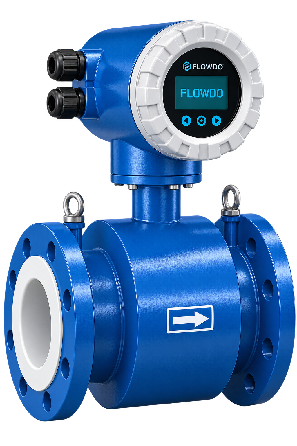
Industrial electromagnetic flow meter for accurate volumetric measurement of conductive liquids with zero moving parts.
View details & specs →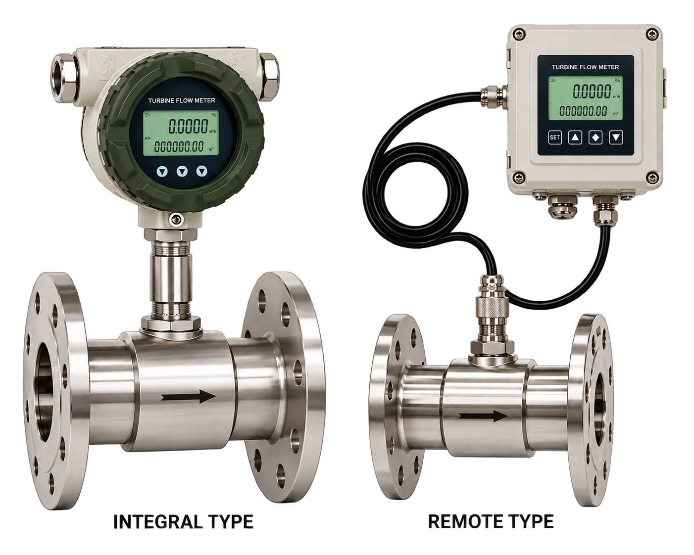
Industrial turbine flow meter for responsive volumetric flow measurement of compatible clean liquids using precision rotor mechanics.
View details & specs →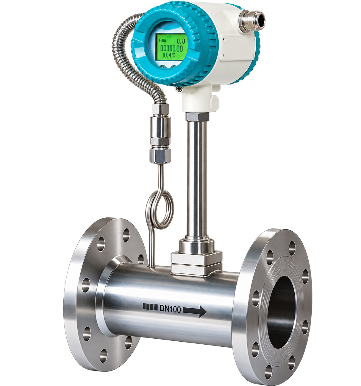
Industrial vortex flow meter using vortex-shedding technology for compatible process-flow applications without moving parts.
View details & specs →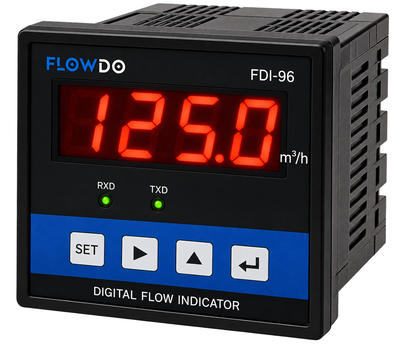
FDI Series High-accuracy panel meter for displaying instantaneous flow rates and totalized volume from compatible pulse and 4–20 mA inputs.
View details & specs →Answers to common technical questions regarding industrial ultrasonic sound-wave flow measurement.
An ultrasonic flow meter determines fluid flow using ultrasonic sound-wave measurement rather than a rotating mechanical turbine.
It compares ultrasonic travel times in the upstream and downstream directions. The difference is related to fluid velocity and therefore flow.
A clamp-on configuration uses transducers mounted externally on a compatible pipe to perform flow measurement without inserting the sensor into the process fluid.
The ultrasonic measurement principle does not require a rotating turbine measurement element.
Yes, suitable water applications can be measured when pipe, fluid and operating conditions meet the requirements of the selected FlowDo model.
Yes. Pipe material, diameter, wall thickness and liners can influence ultrasonic signal propagation and must be considered during configuration.
In clamp-on systems, wall thickness affects the ultrasonic signal path through the pipe and is an important configuration parameter.
Clamp-on FlowDo configurations can provide non-intrusive measurement where confirmed by the selected product.
Suitability depends on the ultrasonic technology. Excessive bubbles or solids can affect transit-time measurement, while some Doppler systems rely on reflective particles or bubbles. Confirm the selected FlowDo technology.
Ultrasonic meters use sound waves, while electromagnetic meters use electromagnetic induction and require a sufficiently conductive liquid.
Ultrasonic flow measurement does not require a turbine rotor, while turbine meters use a rotating mechanical element.
4–20 mA should only be listed for configurations confirmed to support it.
Modbus or other communication protocols should only be shown where confirmed for the selected FlowDo model.
Totalization should only be shown where the selected transmitter supports it.
Yes, where the selected meter output/communication interface is compatible with the automation system.
Only claim IoT Cloud integration where a compatible FlowDo telemetry/interface configuration exists.
Selection depends on pipe diameter, pipe material, wall thickness, fluid, temperature and installation configuration.
Provide pipe size, pipe material, wall thickness, fluid, flow range, temperature, installation requirement and required output.
Share your pipe size, material, wall thickness, process fluid, minimum/normal/maximum flow, temperature, installation requirement and required output with FlowDo to identify a suitable ultrasonic flow-meter configuration.
For faster selection, provide: Pipe Size • Pipe Material • Wall Thickness • Pipe Liner • Process Fluid • Minimum Flow • Normal Flow • Maximum Flow • Process Temperature • Installation Type • Required Output