
Electromagnetic Measurement
Uses electromagnetic induction for volumetric flow measurement of compatible conductive liquids.
Accurate Flow Measurement for Conductive Liquids Without Moving Parts
The FlowDo Electromagnetic Flow Meter measures volumetric flow using electromagnetic induction. Designed for compatible electrically conductive liquids, it provides reliable process-flow measurement without mechanical moving parts in the measuring tube.
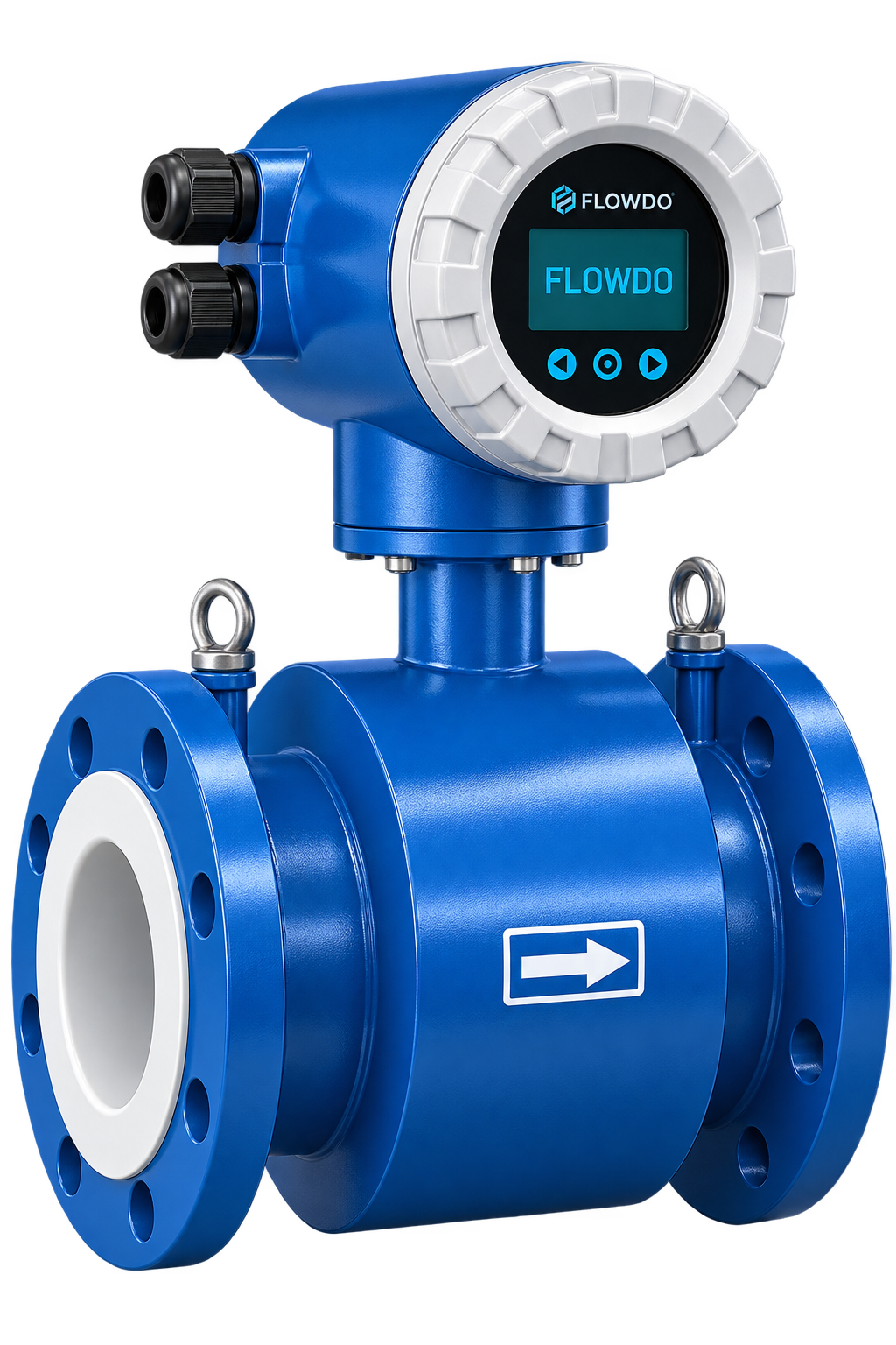
The FlowDo Electromagnetic Flow Meter is designed to measure the volumetric flow rate of compatible electrically conductive liquids.
During operation, the fluid passes through a magnetic field generated across the measuring tube. As the conductive liquid moves through this field, a small electrical voltage is induced. Electrodes positioned in the measuring section detect this signal, and the transmitter electronics convert it into a corresponding flow value.
Because the measurement principle does not require mechanical moving elements in the flow path, electromagnetic flow measurement is well suited to many water, wastewater and industrial process applications.
High-contrast digital readout displays the instantaneous volumetric flow rate on-site in configurable engineering units.
Applicable converter configurations record cumulative fluid volume over time for operational tracking and water accounting.
Transmits a calibrated proportional analog current signal for seamless integration with PLCs, panel indicators, and DCS systems.
Engineered for dependable, high-accuracy industrial liquid metering.
Uses electromagnetic induction for volumetric flow measurement of compatible conductive liquids.
Measurement does not rely on mechanical rotating components in the measuring tube.
Provides continuous volumetric-flow information with rapid dynamic response to flow variations.
Integrated front display delivers clear local reading of instantaneous flow and total volume.
Tracks cumulative volume for batch verification, daily consumption, and billing management.
Standard 4–20 mA current loop and configurable digital outputs for automation integration.
Built for industrial field conditions with high-grade protective enclosures and flanged connections.
Supported transmitter configurations accommodate forward and reverse flow direction tracking.
Delivering measurable performance improvements for plant operators and instrumentation engineers.
The unobstructed measuring tube minimizes pressure drop and avoids mechanical rotor clogging.
Without internal rotating parts, mechanical wear is minimized compared with mechanical velocity meters.
The integrated digital display allows operating personnel to check instantaneous flow and total volume locally.
Standard 4–20 mA transmission facilitates straightforward integration with existing control loops and indicators.
Available liner and electrode configurations can be selected according to supported process requirements.
Compatible transmitter outputs can integrate with PLC and SCADA architectures for process automation.
Comprehensive technical specification architecture for FlowDo Electromagnetic Flow Meters.
The electromagnetic measurement principle requires the process liquid to provide sufficient electrical conductivity for the electrodes to detect the induced signal.
When an electrically conductive fluid flows through the field, continuous charge separation creates a clean electrical signal across the electrodes:
Fluids without sufficient electrical conductivity cannot generate an induced signal detectable by standard measuring electrodes:
Electromagnetic flow measurement does not rely on a turbine, paddle or other mechanical rotor in the flow path.
The liquid passes cleanly through a smooth lined measuring tube while the external magnetic field and flush electrodes perform the measurement without protruding into the fluid stream.
Unlike mechanical velocity meters, there are no rotating rotors, bearings, or pivots subjected to wear, bearing seizure, or fiber entwinement.
Key functional components comprising the sensor body and converter assembly.
Housed in a rugged enclosure, converts induced microvolt electrode signals into flow values and process outputs.
Clear front digital display for instantaneous flow rate and configurable flow totalization indication.
Non-magnetic tube providing an unobstructed passage for the process fluid.
Electromagnetic field coils positioned above and below the tube to generate the measurement magnetic field.
Isolates the metallic tube and prevents short-circuiting of the induced signal across the pipe wall.
Positioned flush in the measuring section to detect the induced potential difference in the flowing liquid.
Heavy-duty bolted flanges on both ends engineered to connect seamlessly to industrial process piping.
Provides an electrical reference between the process liquid and transmitter circuitry for signal stability.
Selecting wetted components around process chemistry, temperature, and operating conditions.
The liner isolates the measuring tube from the process liquid and should be selected according to chemical compatibility, temperature, abrasion and process conditions.
The measuring electrodes contact the process medium and detect the induced flow signal. Their material must be compatible with the liquid and process conditions.
Flow rate, velocity, and nominal bore size work together to achieve optimal measurement performance.
Electromagnetic flow meters determine liquid velocity within the measuring tube and convert it into volumetric flow using the known meter cross-sectional area:
Recommended operating velocity depends on the selected FlowDo meter size and application. Meter size should be selected according to pipeline diameter, expected flow range and desired flow velocity.
For reliable electromagnetic flow measurement, the measuring electrodes should remain appropriately wetted.
When the measuring tube is completely filled with conductive liquid, both electrodes maintain continuous, stable electrical contact across the full cross-sectional area.
If air accumulates at the top of the tube or the pipe runs partially empty, electrodes may lose liquid contact, compromising volumetric measurement calculation.
Key physical mounting practices for reliable electromagnetic measurement.
Meter orientation should be selected to maintain suitable measuring conditions and according to actual process/application requirements:
Disturbed flow caused by elbows, valves, pumps or other fittings can influence measurement conditions. Appropriate upstream/downstream installation should be selected according to the FlowDo meter specification and process layout.
Electromagnetic flow measurement requires an appropriate electrical reference between the meter and process liquid. Grounding requirements depend on pipeline material, meter construction and selected FlowDo configuration (e.g. grounding electrode or grounding rings).
Proven electromagnetic flow measurement across water, wastewater, utilities, and compatible process pipelines.
Flow measurement in compatible raw water, municipal water-treatment and filtration pipelines.
Conductive liquid flow monitoring in suitable sewage and industrial effluent-treatment processes.
Process and utility-water flow monitoring across industrial plants and manufacturing skids.
Flow measurement only where liner and electrode materials are compatible with the chemical medium.
Flow monitoring in compatible cooling tower return, condenser and heat exchanger lines.
Flow measurement in suitable pump discharge, intake and fluid transfer lines.
Distribution network flow monitoring in compatible bulk supply and industrial utility lines.
Only where the selected abrasion-resistant liner, electrode material and application support it.
Discharge flow verification and process liquid monitoring in environmental control systems.
Evaluating fluid suitability based on electrical conductivity and chemical characteristics.
Choosing between no-moving-parts electromagnetic sensing and rotor-based turbine flow measurement.
Technology selection depends on the fluid, flow range, pipe size, required accuracy, pressure, temperature and process conditions.
Comparing electromagnetic induction with ultrasonic acoustic transit-time measurement.
Neither technology is universally better. Selection depends on medium properties, pipe size, installation requirements, accuracy, process conditions and maintenance considerations.
Clarifying the relationship between base electromagnetic sensing and connected telemetry monitoring.
Configurable transmitter models support continuous tracking of momentary rate and cumulative volume.
Current momentary volumetric flow rate value (for example: m³/h, LPM, etc., according to actual configurable transmitter units). Reflects immediate operational conditions in real time.
Accumulated volume over time, essential for water budgeting, batching, billing verification, and compliance records. Preserved across power interruptions on supported transmitter memory.
Seamless signal transmission from field meter into control panels and telemetry architecture.
Define key engineering parameters to select the appropriate FlowDo meter model and materials.
Actual nominal pipeline diameter and internal bore dimensions.
Minimum, normal, and maximum expected volumetric flow rates.
Fluid name, electrical conductivity, viscosity, and chemical composition.
Selected according to chemical compatibility and operating temperature.
Selected according to corrosion resistance and medium compatibility.
Maximum operating process temperature and line pressure rating.
Flange standard (e.g. ANSI, DIN) matching existing piping.
Power supply (230 VAC / 24 VDC), 4–20 mA, pulse, or digital communication.
Explore complementary FlowDo instruments that pair with the Electromagnetic Flow Meter.
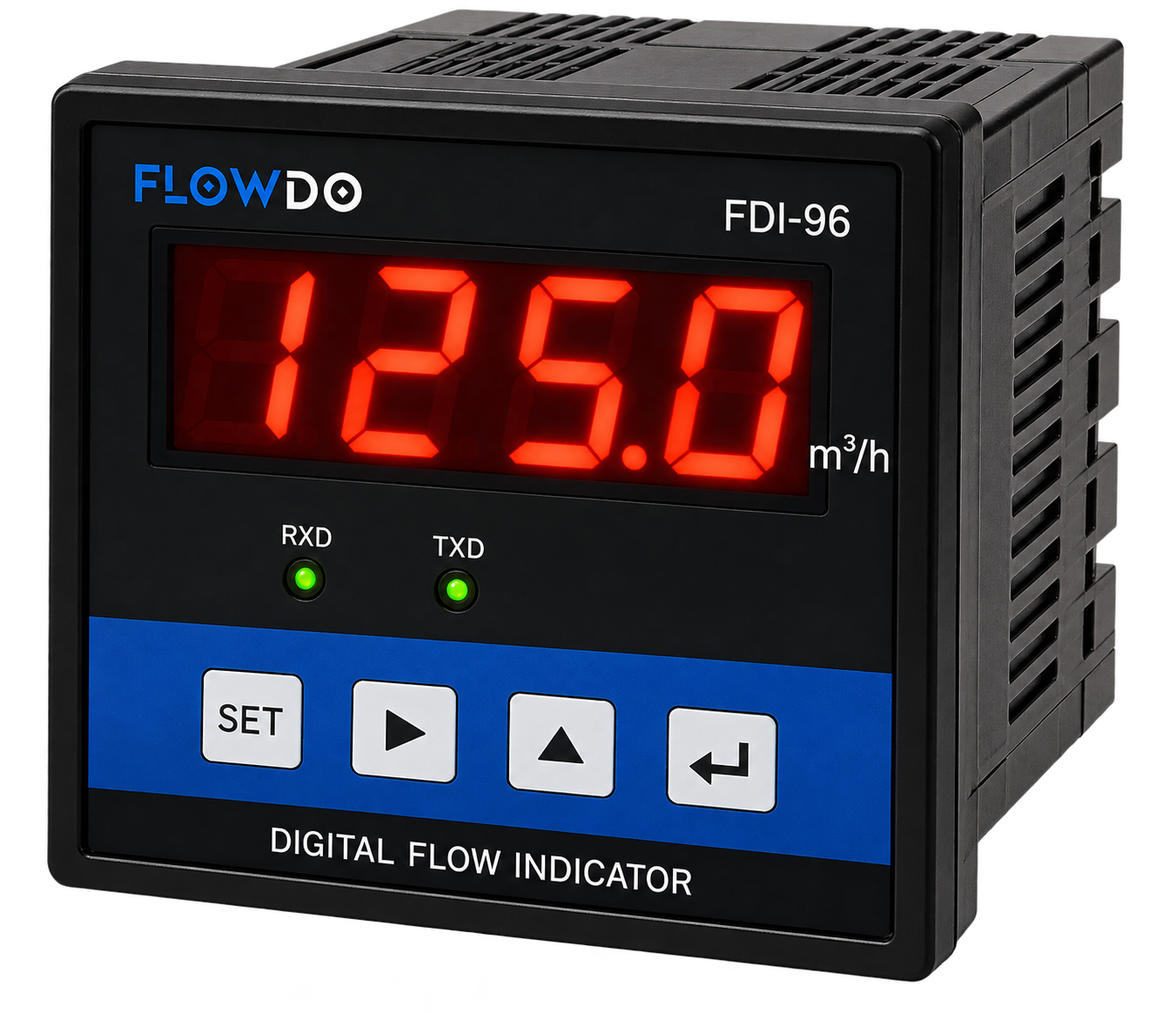
FDI Series Panel-mounted digital process indicator for displaying instantaneous flow rates and totalized volume from compatible 4–20 mA flow meters.
View details & specs →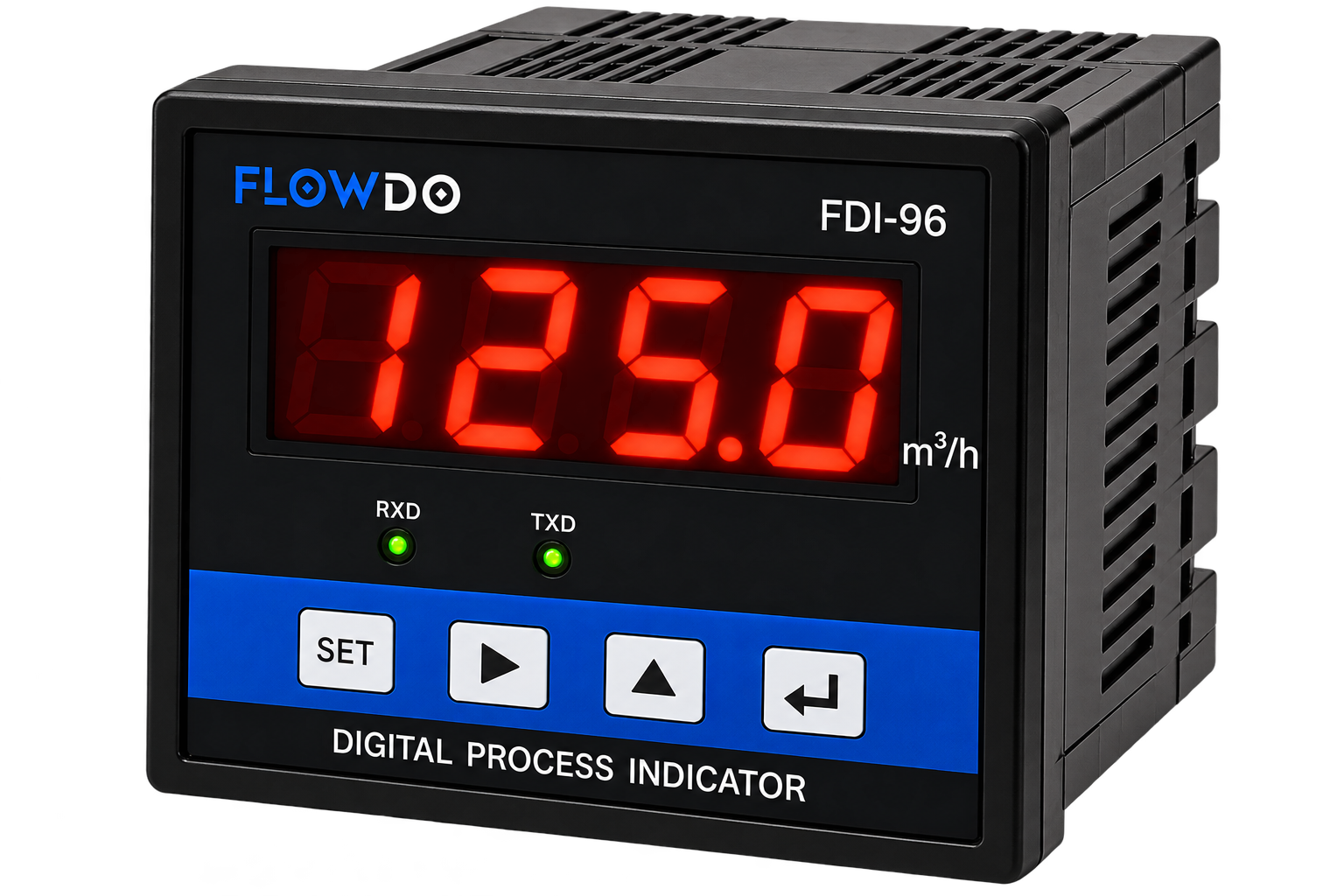
Programmable panel-mounted indicator for monitoring industrial process variables from standard analog transmitter signals.
View details & specs →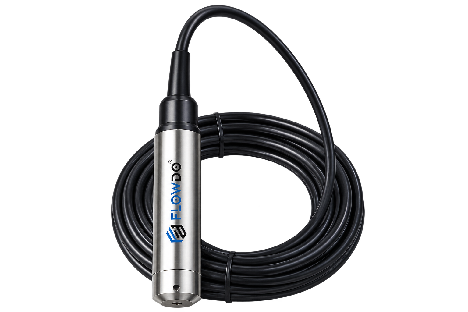
Model FLD-HLT Submersible hydrostatic level transmitter for liquid-level measurement in storage tanks, reservoirs, and sumps.
View details & specs →Answers to common engineering questions regarding electromagnetic liquid metering.
An electromagnetic flow meter measures the volumetric flow of compatible conductive liquids using electromagnetic induction.
As conductive liquid moves through the meter's magnetic field, an electrical voltage is induced. The electrodes detect this signal, and the transmitter converts it into a corresponding flow value.
The electromagnetic measurement principle does not require a mechanical rotor or turbine in the measuring tube.
Water applications are commonly compatible with electromagnetic flow measurement when the liquid conductivity and selected meter configuration meet the required specifications.
Many oils are not sufficiently electrically conductive for standard electromagnetic flow measurement. Actual liquid conductivity should be reviewed before selecting the technology.
Standard electromagnetic flow meters are intended for conductive liquids and are not normally used to measure gases or steam.
The meter relies on electrical interaction between the moving liquid and measuring electrodes, so the process liquid must have sufficient conductivity for the selected meter.
Liner selection depends on chemical compatibility, temperature, abrasion and process conditions. Available liner materials depend on the selected FlowDo model.
The electrodes contact the process liquid and must be compatible with the medium and operating conditions.
4–20 mA is standard on supported FlowDo transmitter configurations for interfacing with industrial indicators and control systems.
Digital communication should be listed only where confirmed for the selected FlowDo transmitter configuration.
Totalization is presented for configurations where the FlowDo transmitter specification confirms this functionality.
Yes, when the selected meter output or communication interface is compatible with the PLC/control-system architecture.
FlowDo IoT Cloud integration can be configured where a compatible telemetry or interface gateway configuration has been confirmed.
Provide the pipeline size, minimum/normal/maximum flow, process liquid, conductivity, temperature, pressure and connection requirements.
Share your pipe size, flow range, process liquid, conductivity, temperature, pressure, process connection and required output with FlowDo to identify a suitable electromagnetic flow meter configuration.
For faster selection, provide: Pipe Size • Minimum Flow • Normal Flow • Maximum Flow • Process Liquid • Conductivity • Temperature • Pressure • Process Connection • Required Output