
Differential Pressure Principle
Measures process flow from the pressure difference created across a calibrated restriction.
Differential Pressure Flow Measurement Using a Precision Restriction Element
The FlowDo Orifice Plate DP Flow Meter determines process flow by measuring the pressure difference created across an orifice plate installed in the pipeline. As fluid passes through the restricted opening, velocity increases and static pressure decreases. A Differential Pressure Transmitter measures this pressure difference, allowing the corresponding flow value to be determined.
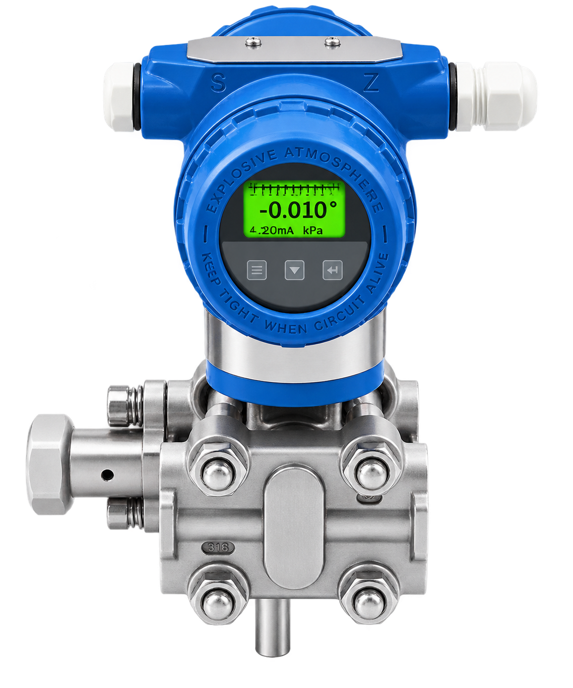
The FlowDo Orifice Plate DP Flow Meter uses a calibrated restriction in the process pipeline to generate a measurable pressure difference.
The Orifice Plate contains a precisely sized bore. As the process fluid passes through this reduced flow area, fluid velocity increases and static pressure changes. Pressure is measured on the upstream and downstream sides of the restriction.
The Differential Pressure Transmitter determines: ΔP = P1 − P2. The resulting differential-pressure signal is then converted into a flow value using the applicable square-root flow relationship and fluid parameters.
High-contrast digital readout displays the instantaneous volumetric or mass flow rate directly in user-selected engineering units.
Transmitter firmware or receiving flow computer performs $Q \propto \sqrt{\Delta P}$ conversion to deliver a linearized flow output.
Transmits a calibrated proportional analog current signal for seamless integration with PLCs, panel indicators, and DCS systems.
For an orifice-type differential-pressure flow measurement system, volumetric flow is approximately proportional to $\sqrt{\Delta P}$.
Where Q represents volumetric flow rate and ΔP represents measured differential pressure across the orifice plate.
Engineered for dependable flow sensing across industrial utility and process piping systems.
Measures process flow from the pressure difference created across a calibrated restriction.
Primary restriction disc engineered for the pipeline diameter, schedule, and flow conditions.
Couples with FlowDo's precision DP transmitters measuring ΔP across HP and LP impulse ports.
No moving mechanical rotors, rotating bearings, or impeller blades inside the flow stream.
Applicable for compatible clean liquids, industrial gases, and saturated/superheated steam.
Local LCD display on the DP transmitter shows differential pressure and instantaneous flow rate.
Outputs standard 4–20 mA DC, HART, or RS485 Modbus RTU communication for plant automation.
Built for industrial process pipelines with standard orifice flange unions and manifolds.
Key operational and economic benefits delivered by FlowDo Orifice Plate DP Flow Systems.
Backed by decades of worldwide engineering standards (ISO 5167, ASME MFC-3M) for primary restriction elements.
The orifice plate contains no electrical wires or rotating parts in the stream, ensuring long mechanical service.
Ideal for high-temperature steam lines using condensation chambers to isolate the transmitter electronics.
If plant flow capacity expands over time, the plate can be re-machined or replaced without modifying piping.
Seamlessly interfaces with plant PLCs, digital flow indicators, totalizers, and telemetry systems.
Provides visibility of both differential pressure (ΔP) and calculated volumetric/mass flow rate.
Comprehensive technical specification architecture for FlowDo Orifice Plate DP Flow Meters.
Widely deployed across power plants, chemical processes, steam generation, and industrial utilities.
Main steam headers, saturated and superheated steam metering, and boiler efficiency balance.
Large-diameter air distribution headers, nitrogen distribution, and industrial fuel gas flow.
High-capacity cooling tower circuits, main pump discharge lines, and raw water distribution.
High-pressure boiler feedwater, auxiliary steam lines, and condensate recovery circuits.
Compatible continuous process streams, chemical transfer lines, and reactor feed pipes.
Facility-wide energy balancing, HVAC hot/chilled water headers, and industrial metering.
Selecting the right flow measurement technology based on fluid properties, conductivity, and allowable pressure loss.
| Aspect | FlowDo Orifice Plate DP Meter | FlowDo Electromagnetic Meter |
|---|---|---|
| Principle | Restriction-based Differential Pressure | Electromagnetic induction (Faraday's Law) |
| Primary Element | Stationary Orifice Plate restriction | Full-bore non-restrictive flow tube with electrodes |
| Pressure Loss | Yes (permanent loss created by restriction) | None (equal to an equivalent length of straight pipe) |
| Fluid Compatibility | Liquid, Gas, Steam (conductivity not required) | Conductive liquids only (≥ 5 μS/cm); no gas/steam |
| Aspect | FlowDo Orifice Plate DP Meter | FlowDo Vortex Flow Meter |
|---|---|---|
| Principle | Differential Pressure across restriction (ΔP) | Vortex shedding frequency behind bluff body |
| Flow Relationship | Square root of DP ($Q \propto \sqrt{\Delta P}$) | Directly linear (vortex frequency ∝ flow velocity) |
| Moving Parts | No moving parts | No moving parts |
| Turndown Ratio | Typically 3:1 to 4:1 (due to square-root response) | Typically 10:1 or higher for compatible velocity |
Detailed technical answers regarding FlowDo Orifice Plate Differential Pressure Flow Measurement Systems.
It is a differential-pressure flow-measurement system that uses an Orifice Plate to create a controlled restriction in the pipeline and a Differential Pressure (DP) Transmitter to measure the resulting pressure difference.
As process fluid passes through the reduced opening of the orifice bore, fluid velocity increases and static pressure changes. The measured pressure difference between the upstream and downstream taps is mathematically related to the flow rate.
The DP transmitter directly measures the static pressure difference (ΔP = P1 − P2) between the upstream high-pressure connection and the downstream low-pressure connection.
No. The transmitter directly measures differential pressure. The ΔP value is converted into volumetric or mass flow through the applicable square-root relationship and engineering flow calculations.
ΔP represents differential pressure — the mathematical difference between the upstream static pressure (P1) and the downstream static pressure (P2).
The plate restricts the flow area, causing acceleration through the bore and localized turbulence. While some static pressure recovers downstream of the vena contracta, part of this energy loss remains permanent in the pipeline.
Beta ratio is the ratio between the Orifice Bore diameter (d) and the pipe internal diameter (D): β = d / D.
Not directly. For an orifice-type DP system, flow is approximately proportional to the square root of differential pressure ($Q \propto \sqrt{\Delta P}$) under the applicable design conditions.
Yes. Orifice Plate DP systems can be engineered for suitable steam and gas applications when designed with proper impulse line configurations and pressure/temperature density compensation.
An impulse line is small-bore tubing that carries process pressure from the pipeline tapping points to the high and low ports of the DP transmitter.
Yes, an analog 4–20 mA output is standard, with optional HART protocol and RS485 Modbus RTU communication.
Yes, through compatible transmitter output interfaces including analog 4–20 mA, pulse, or digital RS485 Modbus RTU.
Share your pipe size, process medium, flow range, pressure, temperature, and fluid properties with FlowDo to engineer an appropriate Orifice Plate and Differential Pressure Transmitter configuration.
For faster engineering, provide: Process Medium • Pipe Size • Pipe Schedule • Minimum Flow • Normal Flow • Maximum Flow • Operating Pressure • Operating Temperature • Fluid Density • Fluid Viscosity • Required Output