
Dual Pressure Input
Measures pressure difference between high- and low-pressure process points.
Accurate Differential Pressure Measurement for Industrial Process Monitoring
The FlowDo Differential Pressure Transmitter measures the pressure difference between two process inputs and converts that measurement into a usable differential-pressure value for local indication, monitoring and compatible process-control systems.
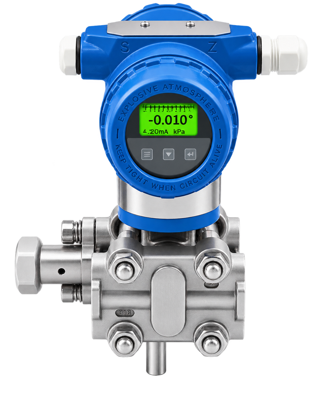
Continuous differential-pressure sensing with dual process connections, integrated digital display and process output integration.
The FlowDo Differential Pressure Transmitter is designed to measure the pressure difference between a high-pressure (HP) process connection and a low-pressure (LP) process connection.
The transmitter's sensing system responds directly to the difference between these two pressure inputs (ΔP = HP − LP). The measured differential pressure is processed electronically and can be displayed locally on the illuminated front display and transmitted to compatible monitoring or control equipment.
Differential-pressure measurement is commonly used where the difference between two pressure points provides meaningful process information, such as pressure drop across filters, flow elements, heat exchangers, or closed-vessel level applications.
Provides immediate on-site ΔP reading for operators to verify filter condition, flow rate, or vessel head pressure instantly.
Clear visual representation of measured differential pressure and operational status on the illuminated front display.
On-board physical interface controls for instrument interaction and parameter review according to selected model.
Rugged circular front housing designed to shield display electronics from dust, moisture, and industrial plant conditions.
Technical specifications vary according to the selected FlowDo Differential Pressure Transmitter configuration. Final values are determined by differential range, static line pressure, sensing technology, output, process connection, materials and application requirements.
Final technical specifications depend on the selected Differential Pressure Transmitter model and process application. For correct technical selection, provide your differential-pressure range, static/line pressure, process medium, process temperature, HP/LP connection arrangement, required output and communication requirements.
Engineered for dependable differential pressure measurement, industrial resilience, and control integration.
Measures pressure difference between high- and low-pressure process points.
Provides continuously changing differential-pressure information for real-time process monitoring.
Integrated display provides convenient local process-value visibility on the shown configuration.
Sensor measurement is electronically processed for indication and supported process output.
Designed for compatible industrial process-pressure applications with rugged field housing.
Available configurations can provide a process signal for remote monitoring and control.
Compatible outputs can interface with industrial PLC, controller and SCADA systems.
Range, connections, materials and output should be selected according to process requirements.
Key operational benefits delivered by FlowDo Differential Pressure Transmitters across industrial systems.
Measures the difference between two process points directly at the sensing cell.
Integrated display provides on-site value visibility on the applicable configuration.
Supported outputs allow differential-pressure information to be transmitted to control equipment.
Pressure difference can be used to understand changes across compatible process equipment.
Compatible configurations can integrate with industrial control systems and indicators.
Range, connection arrangement and process-contact materials can be selected according to available FlowDo configurations.
Understanding the role of dual process pressure inputs on differential-pressure instrumentation.
Distinguishing between the measured differential span and the background static line pressure.
*Conceptual example only — not a product specification.
A DP transmitter measures the net difference between HP and LP (HP − LP). This span is often relatively small (e.g. 0.2 bar across a clean filter).
Both process inputs may simultaneously be exposed to a high common process pressure (e.g. 10 bar line pressure). The sensor housing must withstand this static pressure safely.
The selected transmitter must be suitable for both the required differential-pressure range and the maximum process/static pressure conditions of the piping system.
How the differential pressure transmitter behaves under balanced vs. unbalanced process inputs.
When pressure at both ports is equal, the net mechanical force on the sensing diaphragm is balanced, yielding a zero differential reading.
Conceptual example only.When process resistance causes upstream pressure to exceed downstream pressure, the transmitter accurately senses and outputs the 0.5 bar difference.
Conceptual example only.Common industrial monitoring scenarios utilizing differential pressure measurement.
As a filter accumulates particulate or debris, the pressure difference between the upstream (HP) and downstream (LP) sides increases. Differential-pressure measurement provides vital information about filter clogging and maintenance timing.
In DP flow systems, a restriction (such as an orifice plate, Venturi, or flow nozzle) creates a differential pressure proportional to flow rate. The DP transmitter measures ΔP; flow calculation depends on the primary element, process conditions and configured automation system.
In pressurized closed vessels, the LP port connects to the vapor space while the HP port connects to the liquid bottom. This cancels out vessel head pressure, measuring the hydrostatic head of the liquid column.
Continuous monitoring of pressure drop across heat exchangers, reactor beds, and piping restrictions helps detect scaling, fouling, or internal flow blockages before plant efficiency degrades.
Impulse line arrangements and compatible valve manifold integration for safe transmitter maintenance.
In many differential-pressure installations, process pressure is transferred from the measurement points on the main pipe or vessel to the transmitter's HP and LP ports through suitable impulse piping or tubing.
Impulse-line arrangement depends on the measured medium (liquid, gas, steam), process temperature, transmitter mounting location, and slope requirements to avoid air trapping or sediment accumulation.
A compatible valve manifold (e.g. 3-valve or 5-valve manifold) can support process isolation, zero equalization and safe maintenance operations on differential-pressure installations without shutting down the main process line.
Seamless signal transmission from dual process points into local indication and plant automation architecture.
Comparison of primary FlowDo industrial pressure measurement solutions.
Final selection should be based on pressure range, static pressure, process medium, local-display requirement, connection, output, installation environment and automation requirements.
Reliable differential pressure measurement across industrial processing and plant operations.
Differential pressure measurement across industrial liquid, air, and gas filter assemblies.
Differential-pressure sensing across orifice plates, Venturi tubes, and flow nozzles.
Pressure-drop monitoring across industrial reactors, strainers, and process equipment.
Monitoring differential pressure across tube and plate heat exchangers to detect fouling.
DP monitoring across sand filters, membrane systems, and clarifier processes.
Liquid level measurement in pressurized vessels using vapor-space head compensation.
Differential pressure verification across pumps and balance lines where specified.
Differential pressure measurement across ventilation filters and air handling units where suitable.
General process pressure-difference monitoring and automated control interlocks.
Key technical parameters to define for configuring an optimal differential pressure transmitter.
Minimum, normal, and maximum expected ΔP span, plus required measuring sensitivity and resolution.
HP line pressure, LP line pressure, and the maximum static process pressure the transmitter will experience.
Liquid, gas, vapor, or steam medium, verifying chemical compatibility and viscosity for wetted materials.
Process and ambient temperatures, potential pressure pulsation, vibration, condensation, and outdoor exposure.
HP/LP port thread size, impulse piping arrangement, manifold requirement, mounting bracket, and materials.
Required output signal, power supply, local display, cable entry standard, and PLC / SCADA interface.
Best practices for mechanical mounting, process connection, and commissioning.
Connect process points according to the intended high- and low-pressure measurement arrangement.
Select a DP range appropriate for the expected pressure difference to ensure measurement accuracy.
Ensure the transmitter body and sensor are rated for the actual maximum process line/static pressure.
Confirm wetted-material compatibility with corrosive, abrasive, or aggressive process fluids.
Where used, impulse lines should be arranged appropriately for the process medium, sloping properly to prevent trapping.
Verify process and ambient operating temperature limits to protect transmitter electronics.
Install the transmitter securely using suitable pipe or wall mounting hardware according to guidance.
If used, ensure manifold compatibility with the transmitter and process for safe isolation.
Follow wiring requirements for the selected output and power supply, ensuring proper conduit sealing.
Configuration and commissioning should follow the actual FlowDo model documentation and parameters.
Key configuration parameters required to identify the correct transmitter configuration.
Explore complementary FlowDo instruments for pressure measurement, level sensing and digital process indication.
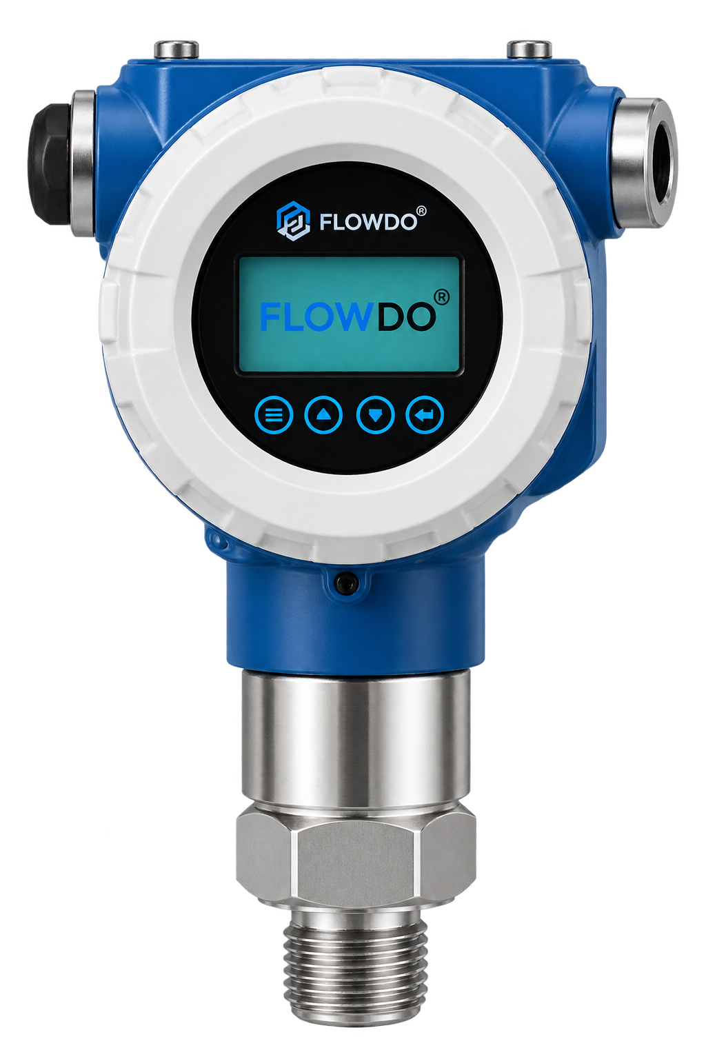
Smart industrial pressure transmitter with integrated digital display for single-point process monitoring.
View details & specs →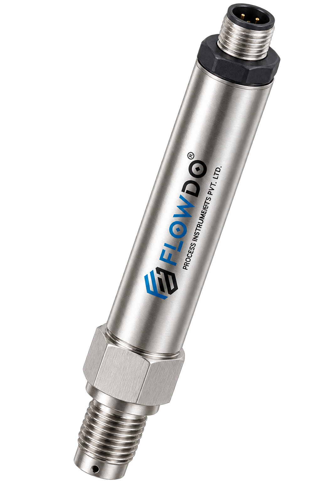
Compact stainless-steel pressure transmitter designed for reliable pressure measurement in tight industrial piping.
View details & specs →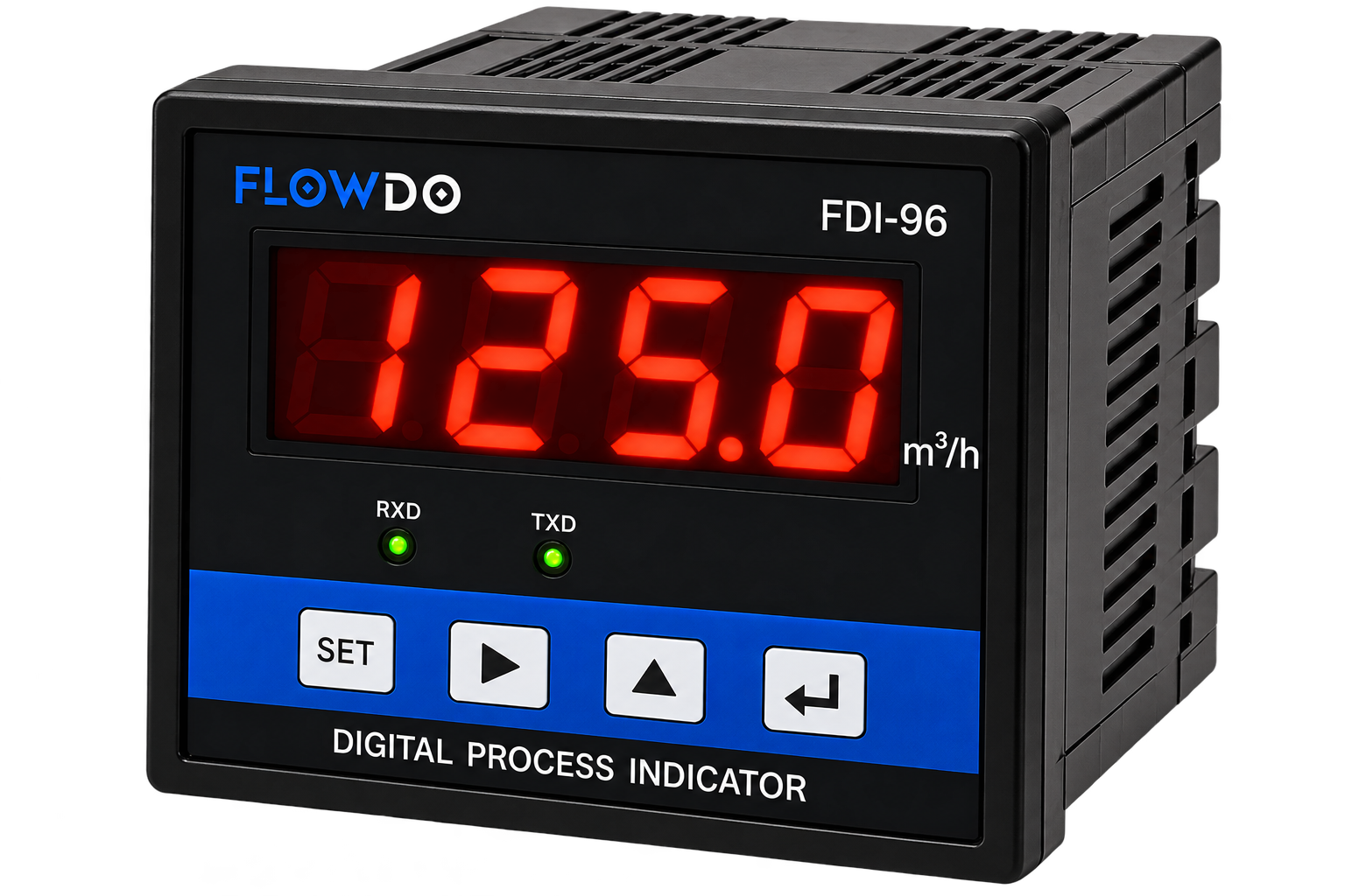
FDI Series Programmable panel-mounted digital indicator for clear local monitoring of transmitter signals.
View details & specs →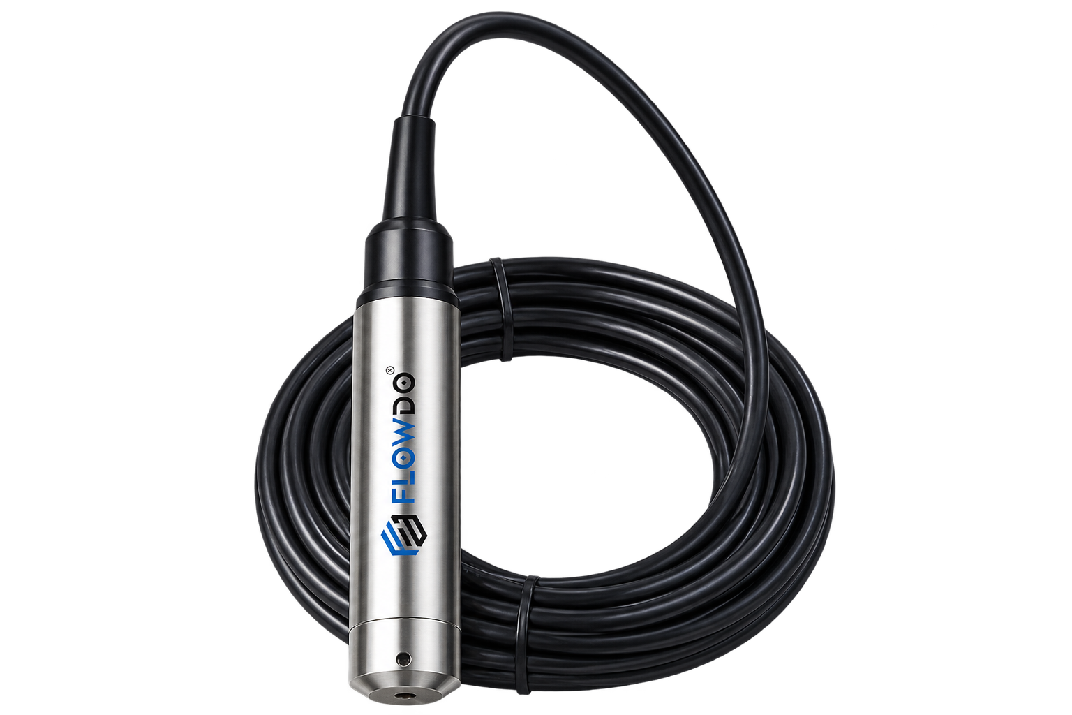
Model FLD-HLT Submersible level transmitter measuring hydrostatic liquid column pressure in tanks and sumps.
View details & specs →Common technical questions regarding industrial differential pressure measurement.
A differential pressure transmitter measures the difference between two process pressure points, generally identified as the high-pressure (HP) and low-pressure (LP) inputs.
Differential pressure (ΔP) is calculated as the difference between the pressure applied to the high-pressure side and the pressure applied to the low-pressure side (ΔP = HP − LP).
A standard pressure transmitter measures pressure at a single process point relative to its reference (gauge or absolute), while a differential pressure transmitter compares two process inputs simultaneously.
HP refers to the high-pressure input port and LP refers to the low-pressure input port of a differential-pressure measurement system.
Yes, differential pressure is commonly used to monitor pressure drop across suitable filters when the installation and transmitter range are correctly selected.
A differential pressure transmitter can be part of a flow-measurement system using a suitable primary flow element (such as an orifice plate or Venturi) and appropriate system configuration. The transmitter itself measures differential pressure.
Differential-pressure measurement can be used as part of level-measurement systems in certain pressurized tank/vessel applications, but proper engineering of process connections, density and pressure conditions is required.
Static or line pressure refers to the process pressure acting on the transmitter inputs in addition to the differential pressure being measured.
The transmitter body and sensor must withstand the actual process line pressure while accurately measuring the much smaller difference between the two ports.
4–20 mA is available for FlowDo configurations confirmed to support standard analog current loop output.
Digital communication options (such as HART or Modbus) are available where verified for the selected FlowDo model and order configuration.
Yes, where the selected transmitter output or communication interface is compatible with the plant automation architecture.
A valve manifold may be used in some differential-pressure installations for isolation and equalization. Requirement and compatibility depend on the selected transmitter and process arrangement.
Provide the expected differential-pressure range, static/line pressure, process medium, process temperature, HP/LP connection arrangement, required output and installation conditions to FlowDo.
Share your differential-pressure range, line/static pressure, process medium, temperature, HP/LP connection arrangement and required output with FlowDo to identify a suitable transmitter configuration.
For faster selection, provide: Differential Pressure Range • Static / Line Pressure • Process Medium • Process Temperature • HP Connection • LP Connection • Required Output • Manifold Requirement